The Machines of David Roth
The pin-wheel mechanism, known from the sketch of Leibniz and machines of Poleni (1709) and Braun (1727) was forgotten for a long time. It was not until about 1840 when two inventors almost simultaneously and probably independently designed pin-wheel calculating machines. First was the Polish Jew Izrael Abraham Staffel (see machine of Staffel), and second was the Austrian Jew David Roth (see biography of David Roth). Actually, there was also an English Jew in this story — David Isaac Wertheimber, who received an English patent №9816 in January 1843, but Wertheimber used the design of Roth’s machines and patented them in England, in order to work as his representative and commercial agent.
David Roth practiced medicine in France and, around 1840, turned his attention to the design and construction of mechanical calculators. In August 1841, he came to London and visited Charles Babbage. The two men discussed the by-then-aborted project of the differential engine.
David Roth intended his calculators to be used in the armed forces, government offices, businesses, and schools. He noted that by understanding the calculator’s mechanical workings, children would better understand arithmetic. He designed many models of calculating devices, which can be divided into two groups — adders and multipliers.
1 Adders
There are many variations on the adding machines of Roth. Some have different capacities. Some have no mechanism for resetting to zero. Others have been adapted for foreign markets. There are simple adders and adder-subtractors. But all share the toothed wheel, the double cam, and the lever.
One of the adding machines of Roth was shown in Vienna in 1842 and in 1844 received a bronze medal at the French National Exhibition of Industrial Products. The Societe d’encouragement pour l’industrie nationale bestowed its silver medal on the adding machine, and it was used by the Navy Department in France.
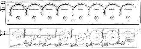
The instrument is enclosed in an oblong teak box. It consists of an upper plate in bronze, pierced by rounded slots through which the toothed wheels of the dials are partially visible. These wheels have twenty teeth on their circumference which correspond to the doubled series of numbers 0.1.2.3.4.5.6.7.8.9.
Jumper springs, made up of a simple flat spring, stop the wheel at each tooth.
On the lid can be inscribed one (for adding machines) or two rows of digits (for adding and subtracting machines). The row outside the slots is used during the addition, while the row below the slots is used during the subtraction (its digits are complementation to 9 of the digits of the upper row.)
The carry mechanism is extremely efficient. Between each pair of wheels, there is an L-shaped lever, fixed on an axle and held by a spring. A double cam underneath each toothed wheel progressively winds up the lever and releases it suddenly. Under the pressure of the spring, the lever acts like a balance and makes the next wheel move forward a notch (one unit).
The mechanism for resetting to zero is equally ingenious. The lower plate has three curved slots over which a flat rod, armed with little pins, moves. When one pulls the rod, it describes a slight semi-circular movement. The small pins act on propellor-shaped pieces which are placed under the double cams. Whatever their position, they are all going to form a horizontal line which, on the dial figures, corresponds to a value of 9. The operator then has only to add one unit with his stylus to pass from 99999999 to 00000000.
Adding machines according to the patents (he was a holder of several patents, e.g. FR13269, FR11462, and FR16536) of Roth were manufactured in many countries around the world — France, Germany, Russia, England, Japan, etc.
2. Multipliers
There are 3 types of multiplication devices, designed by Roth. First is the circle multiplier (see the photo below).
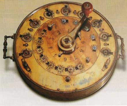
The circle multiplier of Roth (© Musée des Arts et Métiers (CNAM)).
©Unknown author / public domain
The outside circle (so-called) totalizer is composed of a series of nine dials, each with a series of numbers (0-9/9-0). The discs are pierced with 20 holes. The right half is used for addition and the left is for subtraction. The series of numbers are placed semicircular. (They are red for subtraction).
The machine does not have a resetting mechanism. The carry mechanism works like this: there is a series of twenty toothed wheels on which two series of numbers are engraved in double (complementary numbering). As each tooth corresponds to a unit, it’s not one but two little rods, fixed under the wheel, that are going to act, at each half-turn, on a lever that will move the following wheel forward one notch.
Since the machine is round, the dials are positioned on a curved line, but Roth pointed out that he could have made a straight machine without any problem. Between each dial, and unlike the simple adders, turn counters (quotient) have been added (8 counters). Under each dial, a small gear wheel engages with an eccentric pinion which moves the turn counter (quotient).
The mobile middle section is composed of 5 registers and a button to change between addition and subtraction. Each register is composed of a series of numbers engraved on the plate, numbered from 0 to 9, a central disc pierced by a single hole, and a window showing the figures on the dial. When the exterior plate is removed, a large 100-toothed wheel can be seen with five smaller wheels on the same axle as the registers. There are also 5 wheels, called development wheels, based on a pin-wheel mechanism, described by Roth in this way — It’s a copper disc of which one fifth has nine grooves carved into its thickness. The grooves contain nine movable bolts which, when pushed towards the exterior, create as many teeth but which, when retracted into the grooves leave the edge of the disc perfectly smooth. If one of the bolts is moved out of its groove, the disc has one tooth; it has 2 if two bolts are moved out; nine if all the bolts are out of their grooves. On the other hand, it has none if none of the bolts is out of its groove. Each bolt has a pin in the middle which is acted on by a small inclined plane cut into a moving plate which covers the disc and its grooves. It is thanks to this inclined plane that the bolts are moved out of their grooves and returned.
Imagine now that the five development wheels are placed in a circular line on the lower part of the mobile plate, and that the big central wheel has 100 teeth which engage with the twenty toothed pinions of the lower part of the development wheels. Imagine the big wheel divided into ten equal parts and it is easy to see that, while it makes one tenth of a turn, the development wheels make a full turn around their axles.
The big central wheel had one hundred teeth. Imagine that each development wheel has one protruding tooth (i.e. the value 11111 on the registers). If the big wheel makes a tenth of a turn, the development wheels are going to add one unit to each of the totalizers and, therefore, mark 11111. If it makes 4-tenths of a turn, the totalizers will show 44444.
The operator indicates the value of the multiplier on a circular dial with a moving pointer placed on the same axis as the crank. When the value is reached, the pointer comes up against a stop hook. The crank never makes a complete turn; a ratchet always makes it return to its starting position.
The moving part (carriage), is in the central section, where the registers are. Quite simply, one releases it by pressing a button. Then one only has to place the first development wheel on the right in front of the unit dial of the outer circle to begin the operation.
In order to prevent too high speeds in the mechanism, resulting in wheels overturning too far, Roth provided a fly-brake.
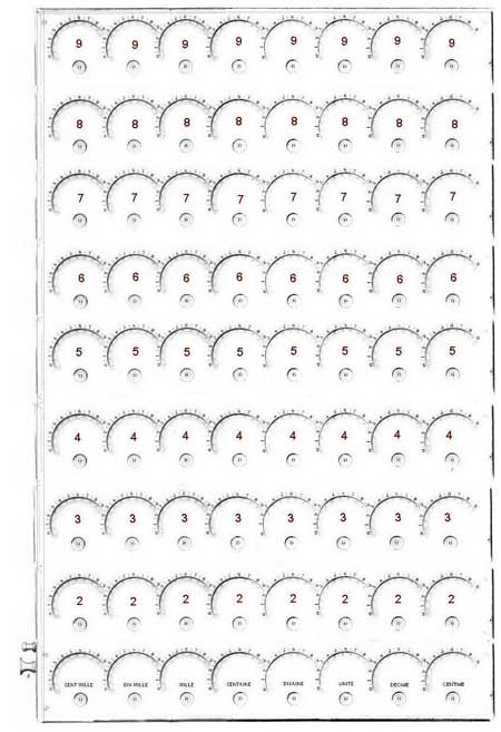
The second multiplication device of Roth is the so-called permanently engaged multiplier. This is a multiplier, which is much simpler and cheaper than his superb variable-toothed circular multiplier.
Roth used for this multiplier the construction of the adding device, but added to each dial gear trains which form a series of continuous gearings. Above each dial, eight other dials are arranged vertically and linked mechanically by pinions so that these turn in the same direction and have a particularity in that their speed increases progressively by one-tenth from bottom to top. In short, when the top dial (of 9’s) has completed a turn, the 8’s dial will have done 2, etc. and the adder (totalizer) dial will have done 9. Since this one has a carry, the result obtained will be 81.
Imagine it with a capacity of eight figures. It would then have 72 dials, which would not be simple to manufacture.
For each decade there would be nine dials. The lower one is the totalizer dial of the adder. The others correspond to the multiples 2, 3, 4, 5, 6, 7, 8, and 9.
Under the plate and for each multiple there is a 20-toothed dial wheel, armed with a jumper spring, and carrying the numbering 0.1.2.3.4.5.6.7.8.9. 0.1.2.3.4.5.6.7.8.9, two gear wheels with 90 teeth placed one above the other for the 9’s multiple, two 80-toothed wheels for the 8’s multiple, etc. These gear wheels were doubled up, probably for strength reasons. Intermediary pinions also doubled up, have a number of teeth inversely proportional to the gear wheels in order to maintain an equal distance between each dial.
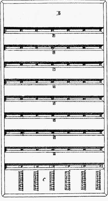
The third type of multiplication device, designed by Roth is so so-called multiplier and divider with small rulers (Multiplicateur et diviseur à réglettes) (see the patent drawing in the nearby figure). Roth imagined a very ingenious system for multiplying and dividing with small rulers. In this new setup, nine series of figures, one above the other, are printed on a small cardboard ruler.
They show the multiple of each number from 1 to 9. The instrument, with a capacity of 6 figures, has 6 small rulers which overlap partially. Small, carefully positioned cutouts show “the excess of transmission of the unit on ten”. In short, it’s a matter of spreading the product of multiplying one figure by another over two orders of decimals.
The small rulers are placed in a wooden frame, containing 9 horizontal windows (for each multiple).
The bottom section has six vertical slots with cursors which allow the small rulers to be moved up and down in order from 0 to 9.
The image featured at the top of this post is ©Unknown author / public domain