Key Points:
- Between 1872 and 1898, American George Barnard Grant patented and manufactured several models of calculating machines through his company Grant Calculating Machine Company of Lexington, Massachusetts.
- Grant exhibited his Centennial Model calculating machine in his home state at the Fourteenth Exhibition of the Massachusetts Charitable Mechanic Association, Boston, in 1881, and won a gold medal.
- Grant won an award for his invention, which was described as “superior to all other instruments of its class yet produced.”
George Grant’s Calculating Machines
Between 1872 and 1898, the American George Barnard Grant (see biography of George Barnard Grant) of Cambridge, Massachusetts, patented and manufactured in his company Grant Calculating Machine Company of Lexington, Massachusetts, several models calculating machines. He received four patents for calculating machines — in 1872 (US Patent №129335), 1873 (№138245), 1887 (№368528) and 1888 (№605288).
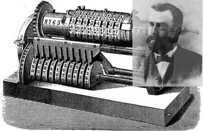
In 1876 Grant exhibited two calculating machines at the 1876 USA Centennial Exposition in Philadelphia. The first was a magnificent differential machine. The second exhibited machine was a smaller calculating device (also known as the grasshopper adding machine), which was described in the first two patents from 1872 and 1873 (see the figure below). In the official report of the United States Centennial Commission is mentioned:
The most important exhibits of this class [Mechanical Calculation] were the two calculating machines of Mr. George B. Grant, of Cambridge, Massachusetts, the larger one of which is arranged to combine and print functions involving 100 elements. The combination of the several parts is extremely simple; the number of elements can be indefinitely increased, and the machine acts with the greatest certainty. The smaller machine, or arithmometer, is an adding-machine, which successfully rivals the well-known one of Colmar. The adding-machine of Petersson, of Norway, also deserves special mention here.
The abovementioned arithmometer was a device, made from 400 parts, 30 cm long and 15 cm high, and was later sold for $100. Several copies were built and are to be found in the Smithsonian and private collections, but the machine was never placed in commercial production. Grant was able to get this device to operate rapidly (…a poorly made apparatus has been worked at the rate of 10,000 operations per minute with perfect accuracy) and may well have used this as part of his experiments to produce other calculating machines.
Grant is reported to have invented this machine (the so-called Centennial Model) while a student at the Lawrence Scientific School of Harvard University (between 1870 and 1872). This machine was reported to be intended for use in counting houses, insurance offices, etc., and was described as a smaller instrument for common operations in multiplication, division, etc. It is a foot in length by half as much in height and width, weighs twenty pounds, and contains less than 400 pieces, less than 75 of which are working parts. It takes numbers up to nine decimal places. According to an exhibition report, this machine, or arithmometer, successfully rivals the well-known one of Colmar.
In 1881, Grant exhibited the calculating machine in his home state at the Fourteenth Exhibition of the Massachusetts Charitable Mechanic Association, Boston, 1881, and won a gold medal. The report of the exhibition stated: This calculating machine has now stood the test of practical use, several of the machines having been employed during the past three years. It is admirably adapted for an extensive range of computations in multiplication and division and surpasses all other instruments now used for such computations with respect to simplicity, strength, compactness, durability, cheapness, rapidity, and accuracy of operation
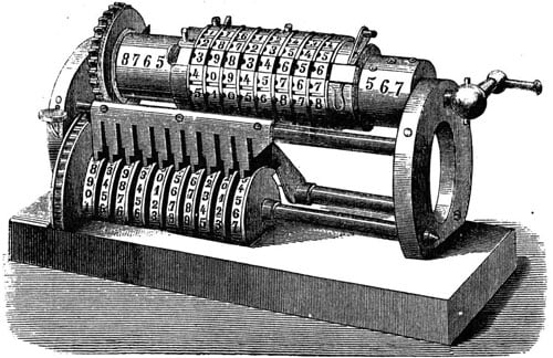
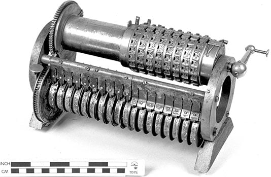
The barrel-type, non-printing machine (overall measurements: 18.6 cm x 46.3 cm x 15 cm) has a rectangular wooden base, cut out to allow for the motion of a set of wheels that rotates on a shaft near the bottom. This shaft is linked to a larger upper cylinder by gears so that the wheels and the cylinder turn simultaneously when a handle at the right end of the upper cylinder is rotated. The frame for the instrument consists of hollow discs at opposite ends of the base, which are connected to the two shafts already mentioned, and a third shaft which carries a set of 20 spring claws that link to the gears of the wheels.
Part of the upper cylinder has a metal collar that can be set at any of 18 positions on the cylinder with a locking pin. This collar supports 18 movable rings. Each ring has an adding pin and a stud on it which may be set at any of ten positions, labeled by the digits from 0 to 9. The lower cylinder has 20 recording wheels on it, each provided with 30 teeth. The digits from 0 to 9 are stamped three times around each wheel. The spring claws fit the gears of the recording wheels. If a claw is pushed down, it engages the gear of the recording wheel, causing it to rotate. Studs on the wheel lead to carrying by engaging the next claw over.
This model has no mechanism for displaying the multiplier or multiplicand. A flat disk at the end of a lever on the left side serves as a brake on the operating wheels, indicating when the operating crank has been turned through one revolution.
The judges at the Centennial Exhibition gave Grant an award for his invention, and described his machine as “superior to all other instruments of its class yet produced.” It was lauded by actuaries and distinguished professors, but never gained large sales. This version of the machine was sold for $100.
In 1898, Encyclopaedia Britannica reported that there were numerous crank-operated calculating machines for multiplication and division, including machines made by Thomas, Tate, Odhner, Baldwin, and Grant. “Grant’s machine consisted of a cylinder bearing a set of rings on which were the numerals. These he terms adding-rings. A similar set of rings is placed on a shaft below, and these he terms registering wheels. In order to multiply, the adding-rings are set to read the multiplicand, and the registering-wheels the multiplier. If the multiplicand was 387432, the crank would be turned three times and a slide shifted, then eight times and a slide shifted, and so on. At the conclusion of the turning the answer could be read on the recording-wheels.”
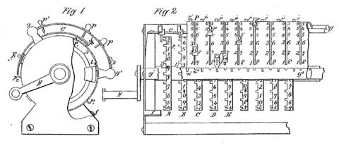
The numbers are entered through the openings of the lid (marked within the patent drawing), mounted on the sliders and g’. The results are shown on the digital wheels (which are similar to teeth-strips), placed under the lid. Adding the number is performed by means of the movable carriage, which can be rotated by means of the handle. On the lid are cut-off slots (or openings in the first patent), into which are pushed in the pin. The slots (openings) are graduated with the digits from 1 to 9 and the number is entered by pushing in the pins in the appropriate openings, while the lowest row is for units, the upper row is for tens, etc. In this way, the entered number can be multiplied by 10 or divided by 10 (by moving upwards or downwards of the lid to one division). Besides the graduated digits are inscribed smaller digits (from 9 to 1), which are complementing to 9 of the bigger digits and are used during the subtraction and division. The digital wheels A, B, C, D, and so on, are placed below the slots, and each wheel is divided by two (or three) groups of 10 teeth, each tooth is marked with a digit.
The machine has also a mechanism for zeroing the display of digital wheels.
The pins act as a stop for placed below digital wheels, which during the rotation of the handle (carrier) make a motion forward-backward and transfer the numbers from the input to the displaying mechanism.
In his patent from 1873 George Grant suggested three variants of the tens carry mechanism, depending on the capacity of the machine.
The arithmetical operations with the machine are performed in the typical for the adding machines way, keeping in mind, that the calculating mechanism can be rotated only in one direction and during the subtraction and division is used complementing to nine.
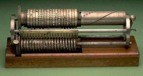
The U.S. Patent Office model for the last machine of Grant is still preserved in the National Museum of American History (see the photo below).
The model (overall measurement: 19.5 cm x 34.3 cm x 14.4 cm) has a rectangular wooden base. The frame is made up of two plates at either end of the base connected by metal shafts. The mechanism has a large upper cylinder and a small lower cylinder linked by gears of equal size. Fifteen centimeters of the upper cylinder has a metal collar that can be set at any of eight positions on the cylinder. This collar supports eight movable rings, each of which represents a digit entered. Each ring has an adding pin and a stud on it that may be set at any of 10 positions, labeled by the digits from 0 to 9.
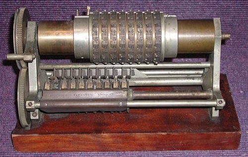
The lower cylinder has 10 recording wheels on it, each provided with 30 teeth. Paper loops numbered from 0 to 9 three times run around each wheel. On a bar between the cylinders is a row of ten spring claws, one for each recording wheel. If a claw is pushed down, it engages the gear of the recording wheel, causing it to rotate. Studs on the wheel lead to carrying by engaging the next claw over. The model has no mechanism for displaying the multiplier or multiplicand.
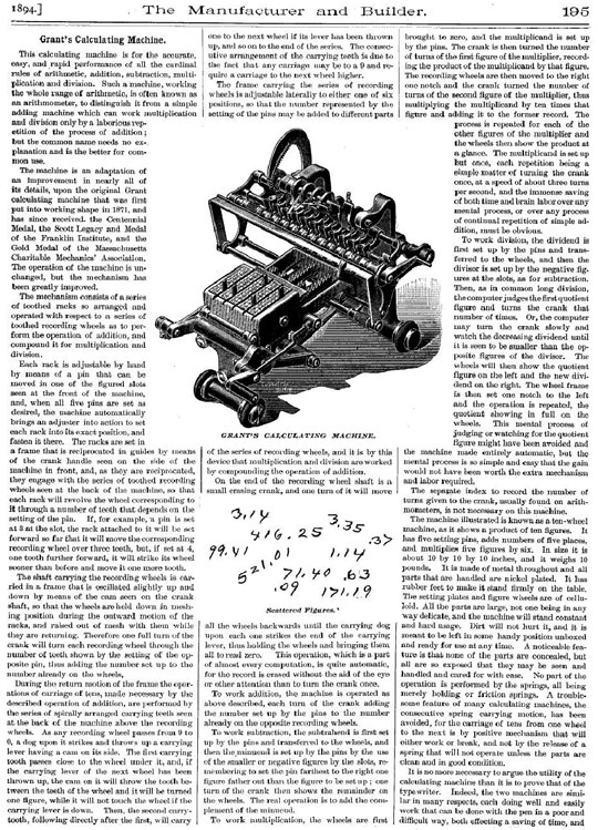
Later on, Grant redesigned the machine, adding a printing device, and manufactured his calculator (advertised as a “ciphering hand-organ”) with some success (about 125 machines were sold) until the end of the 19th century. The last calculating machine of Grant (called Grant’s grasshopper model because of its appearance) was exhibited by George Grant at the Columbian Exposition held in Chicago in 1893 and was described in the journal Manufacturer and Builder, vol. 26, issue 9 (September 1894) (see the figure below). Later on, Grant designed an experimental model, designed to incorporate subtraction and division as well as addition and multiplication.
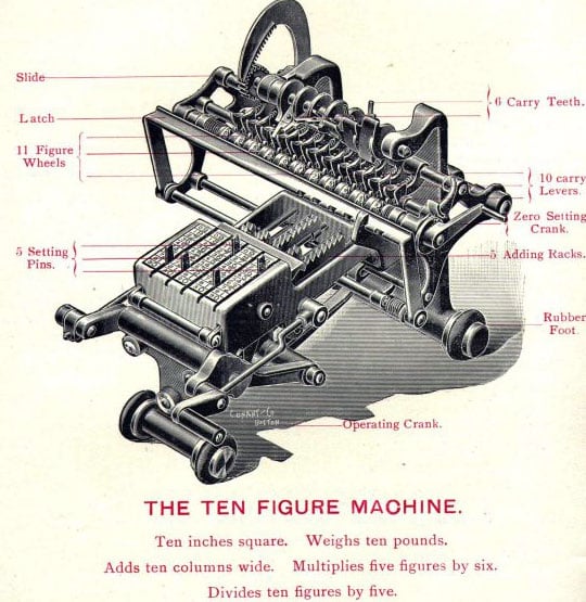
The machine (overall measurements: 20.7 cm x 24 cm x 27.5 cm) has an open iron frame painted black, with steel and brass parts and paper labels. Five sliding pins at the front of the machine are used to set numbers on racks beneath. Next to each pin is a thin strip of paper with the digits from 0 to 9 printed on it. The digits increase as one goes toward the back of the machine. Each strip also has complementary digits in smaller type, for use in subtraction and division. Moving back a pin drives back a toothed rack.
Behind the racks is a movable carriage with 11 gears on it. A paper strip with digits on it is next to each gear. Turning a crank at the front right of the machine moves the racks back to engage the gears, turning each one of them in proportion to the number set. When the adding frame reaches the end of its backward movement, a cam set on the crankshaft at the front raises all the register gears a little so that the gears are disengaged from the racks and not moved in the return motion. One tooth on each gear extends so that when the gear has made a complete rotation, it engages one of the carry teeth arranged on a spiral shaft above the carriage. As the adding racks return to position, the shaft revolves and the carry tooth pushes the next gear up by one, resulting in a carry. The result appears on the paper strips between the gears on the carriage.
The image featured at the top of this post is ©Unknown author / public domain