
Electromechanical Relay

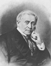
The electromechanical relay, used as a constructive part of some early calculators and computers (see computers of Zuse, Aiken, and Stibitz), was invented in 1835 by the brilliant US scientist Joseph Henry (1797–1878), known mainly as the inventor of the electromagnetic phenomenon of self-inductance and mutual inductance (see the nearby photo for Henry’s electromagnet from 1831). Henry was only really interested in the science of electricity and the relay was a laboratory trick to entertain students.
Henry’s invention was based on the work of the British electrical engineer William Sturgeon (1783–1850), a former shoemaker and soldier, who began to dabble in the sciences at the age of 37, and who invented the electromagnet in 1825.
Samuel Morse later used Henry’s relay device to carry morse-code signals over long kilometers of wire, but generally, the invention of Henry remained relatively unknown for several decades. In the 1860s, and later on at the end of the 19th century, with the development of telegraph and phone communications, it became widespread.
Especially after the invention of the rotary dial, first developed in the USA by Almon Strowger in 1890, which however used not the simple two-position switches described below, but ten-position relays, the phone companies became huge consumers of electromechanical relays.
What is the construction of a typical relay, used in telephone switching (see the lower drawing)?
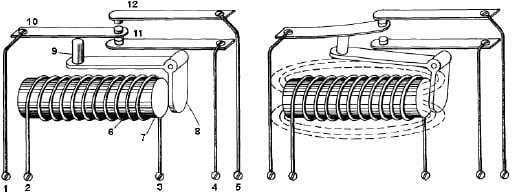
A typical electromagnetic relay, used in telephone switching (left, de-energized, right—energized status)
A typical electromagnetic relay consists of an electromagnet (an iron bar, marked with a 7 on the drawing, and a coil of wire, marked with a 6), an iron armature (8), with a fixed pin of insulator (9), and 3 contacts: normally closed (11), normally opened (12) and common (pole) contact (10).
In normal de-energized status (left part of the drawing), to the electrical terminals (2) and (3) is not applied voltage, the electromagnet is not powered and contacts 10 and 12 are not connected, so the current is not flowing between common contact (10) and normally open contact (12).
If a voltage is applied to the contacts (2) and (3) of the coil (right part of the drawing), then the electromagnet will be powered, thus attracting the iron armature, and insulator pin (9) will push the plate of the common contact (10), thus making a contact between it and the normally open contact (12). The electrical loop will be closed and current will go from the common contact (10) to the normally open contact (12). When the voltage is canceled, then the armature will fall down, and the contact will be opened again.
It is clear, that the relay is an ON-OFF device, a switch, suitable for building logical circuits. By the beginning of the 20th century, a number of inventors recognized that the ability (as well as the power) offered by electric circuits allowed one to build a machine that could not only do arithmetic but also direct a complex sequence of calculations automatically (see for example, Leonardo Torres).
Devices of these types were in common use by the 1930s. Simple relays cost a few dollars each, and they were fairly rugged and reliable. But, for ordinary calculators, the relay offered few advantages over mechanical cams and gears. It was still cheaper and more reliable to store or add a decimal number on a train of ten-tooth gears than on a bank of multiple-contact relays.
But, for something more than simple arithmetic, relays had a crucial advantage over mechanical systems, in that their circuits could be flexibly arranged (and rearranged) far more easily.
One could arrange relays on a rack in rows and columns, and connect them with wires according to what one wanted the circuit to do, then he could further reconfigure a relay system using a switchboard, with cables plugged into various sockets.
Going a step further, one could use a strip of perforated paper tape (originally developed to store telegraph messages for later transmission), to energize a separate set of relays that in turn reconfigured the system just as the plugboards did.
In this latter instance, the same relays perform the functions of both arithmetic and control. This seems to confer little advantage over mechanical calculators, as it appears that arithmetic and control are two different activities. But, in fact, the two are closely related, and for anything more than simple arithmetic both are required.
A calculator designer who uses relays may exploit their ability to do both tasks, thus enabling the design of a machine with the general capabilities of Babbage’s Analytical Engine, but with a much simpler overall design.
The image featured at the top of this post is ©Unknown author / public domain