
Edmund Dana Barbour (Source: Harvard University Archives, HUGFP 125.32, Box 1, Folder Barbour)
Edmund Barbour
In 1872, a certain Edmund D. Barbour from Boston, Massachusetts, received two very interesting US patents for calculating devices (U.S. patents №№130404 and 133188), describing a machine, which seems to be the first representative of so called direct-multiplication devices (in the same 1872 Barbour received also a patent in Great Britain (GR187202437) and in France (Brevet N°96190). In his second patent, he not only improved and simplified his first machine but also provided a simple printing mechanism.
Besides that, in 1875 Barbour patented a new machine (U.S. patent №168080), not a direct-multiplication one, but with a more complex printing device. Barbour seems to be one of the first people (after Müller and Babbage), who designed a printing mechanism for his mechanical calculator.
Besides these three patents, we don’t have any other information about the inventor (Edmund D. Barbour, according to the patent application) and if his machines were manufactured (most probably they had not been commercialized, to my mind they were too advanced for the time).
According to my personal investigations, the inventor was Edmund Dana Barbour (1841-1925), a local Boston businessman, philanthropist, and genealogist — an heir (8th generation) of the glorious family of Captain George Barbour (1615-1685), the Puritan leader of Dedham and Medfield, who came to America in 1635 (see biography of Edmund Dana Barbour).
Most early calculating machines carried out multiplication as a form of repeated addition. To multiply, say, by sixteen, one set the carriage at its rightmost position, turned the operating crank six times, shifted the carriage one position to the left, and turned the crank once. In direct-multiplication calculating machines, the operator had only to perform operations when the multiplier was a digit number.
Let’s start our review with an examination of the first direct-multiplication device of Barbour, and obviously the first of its kind in the world.
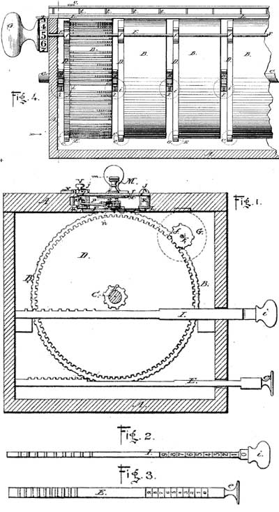
The patent drawing of the first machine of Barbour
The accumulator mechanism of the machine, including the numeral wheels and their devices for transferring the tens, is mounted in a sliding carriage at the top of the machine (see Fig. 1 of the patent drawing), which may be operated by the hand-knob. Extending through the bottom of the carriage are a series of pinions, one for each ordinal numeral wheel, and connected thereto by a ratchet and pawl action. The pinions are each so arranged as to be operative with a gear rack beneath the carriage when the carriage is slid back and forth.
Thus the wheels received action from one direction of the motion of the carriage and remained idle during the movement in the other direction. The degree of motion so received would, of course, depend upon the number of teeth in the racks below encountered by the pinions.
The gear racks employed by Barbour were numerous, one being provided for each multiple of the nine digits, arranged in groups constituting nine sets mounted on the drums marked (see Fig. 4). Each of these sets contain nine mutilated gear racks, the arrangement of the teeth of which serve as the multiples of the digit they represent.
The teeth of the racks representing the multiples of the digits were arranged in groups of units and tens. For instance: 4×6=24, the rack representing the multiple of 4×6 would have two gear teeth in the tens place and four gear teeth in the units place, and likewise for the eighty other combinations.
Adding the multiples of the digits by overlapping the orders was accomplished by a very simple means, the arrangement of the racks being such that as the carriage was moved from left to right the numeral wheel pinions would move over the units rack teeth of a multiplying rack of one order and the tens rack teeth of a multiplying rack in the next lower order.
By close examination the reader will note from the drawings that the lower one of the sets of multiplying gear racks shown on the drum, to the left in Fig. 4, is the series of one times the nine digits, the next set or series of racks above are the multiplying racks for the multiples of two, the lowest rack in that series having but two teeth, the next higher rack four teeth, the next rack six and the next eight.
So far no multiple of two has amounted to more than a unit ordinal place, therefore these racks operate on a lower-order numeral wheel and are all placed to the right of the center on the drum, but the next rack above for adding the multiple of two times five requires that one shall be added to a higher order, and is therefore placed on the left side of the center of the drum.
Thus it will be noted that by reading the number of teeth on the right of each rack as units and those on the left as tens, that running anti-clockwise around the drum, each series of multiplying racks shows multiples of the digits from one to four, it being obvious that the racks for adding the multiples of the higher digits are on the opposite side of the drums.
From the layout of the racks it is also obvious that the starting or normal position of the carriage would be with the numeral wheel pinions of each order in the center of each drum, so that as the carriage is moved to the right, the units wheel will receive movement from the units teeth of the rack on the units drum, while the tens wheel will receive movement from the units teeth of the tens drum and the tens teeth of the units drum, and so on with the higher wheels, as each numeral wheel pinion except the units passes from the center of one drum to the center of the next lower and engages such teeth as may be presented.
Each of the drums is independently mounted on the pivot shaft and is provided with the hand-operating setting racks and, co-acting with the gears to help in bringing the proper racks into engageable positions with the pinions of the accumulator numeral or total wheels.
The hand-knob, Fig. 4, and the gears, fast to a common shaft, furnish a means for operating the whole series of drums when the right multiple series of racks of each drum have been brought into position.
As an example of the operation of the Barbour calculator, let us assume that 7894 is to be multiplied by 348. The first drum to the right would be moved by its setting racks until the series of multiplying racks for adding the multiples of four are presented, the next higher drum to the left would be set until the series of multiplying racks for adding the multiples of nine were presented, the next higher drum would be set for the multiples of eight, and the next higher drum, or the fourth to the left, would be set for the multiples of seven.
Then the hand-knob, first turned to register zero, may be shoved to the right, engaging the pinions with the gears, and by turning the knob to register (8), the first figure in the multiplier, the racks are then set ready to move the numeral wheels to register as follows: The drum to the right or the units drum has presented the multiplying rack for adding the multiple of 8×4, thus it will present three teeth for the tens wheel and two teeth for the units wheel.
The tens drum presenting the rack for adding the multiple of 8×9 will present seven teeth for the hundreds wheel and two for the tens wheel. The hundreds drum presenting the rack for adding the multiple of 8×8 will present six teeth for the thousands wheel and four for the hundreds wheel.
The rack of the thousands drum representing the multiple of 8×7 will present five teeth for the tens of thousands wheel and six for the thousands wheel. Thus by sliding the carriage to the right one space, the numeral wheel pinions will engage first the unit teeth on one drum, then the tens teeth on the next lower drum and cause the wheels to register 63152.
The operator, by turning the knob to register (4), the next figure of the multiplier, turns the drum so that a series of multiplying racks representing multiples of 4 times each figure in the multiplicand are presented, so that by sliding the carriage another space to the right, the multiple of 4×7894 will be added to the numeral wheels. The operator then turns the knob to register three and moves the carriage one more space to the right, adding the multiple of 3×7894 to the wheels in the next higher ordinal series, resulting in the answer of 2747112.
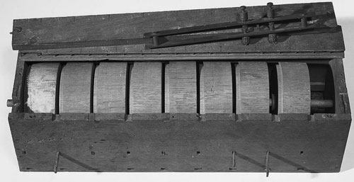
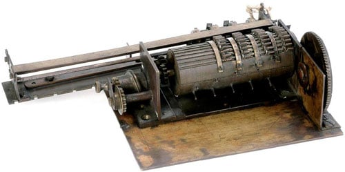
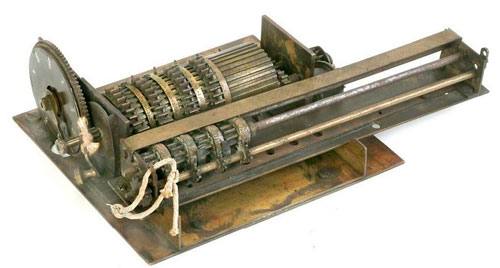
The first calculating machine of Edmund D. Barbour (Courtesy of the Smithsonian Institution)
The U.S. Patent Office model (up to 1880, the Patent Office required inventors to submit a model with their patent application) of the first calculating machine of Edmund D. Barbour’s is still preserved in the National Museum of American History (see the upper photo).
The patent model is a greatly simplified version of the patented machine, with overall measurements: 14 cm x 41 cm x 13 cm. It consists of eight wooden cylinders that rotate on a crosswise shaft inside a wooden box.
Each cylinder has around its edge 90 rows of cog teeth (they have not actually been constructed, only shown as pen marks on a slip of paper that extends around the first cylinder). Each set of nine cog teeth represents the multiples of a digit (zero multiples correspond to blank spaces).
The machine is set to a given multiplier by rotating all the cylinders with a knob at one end of the machine (this knob is also missing). The first cylinder has on its left side a wooden spur gear with 90 teeth. The other cylinders would have such gears, but they are uncut. Pulling out a wooden toothed rack below the gear advances it one-ninetieth of a revolution for each unit on the rack. Hence the operator can set a multiplicand.
A movable carriage of brass on the top of the machine is supposed to be linked to the cylinders so that when the carriage is pulled one unit to the right, the recording wheels advance in proportion to the figure represented on the edge of the cylinders (in the model, the cylinders are not linked to the sliding carriage).
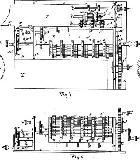
Now let’s examine the second patent (see the lower drawing) for an improved and simplified variant of the first machine with a printing mechanism.
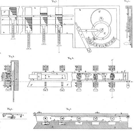
The patent drawing of the second machine of Barbour
The printing device for recording calculations was of the most simple nature, allowing only for the printing of totals and sub-totals. Its manipulation consisted of placing a piece of paper under a hinged platen and depressing the platen by hand in the same manner that a timestamp is used. The ink had to be daubed on the type by a hand operation to make legible impressions of the type.
Fig. 1 represents the base of the machine, while Fig. 4 shows a carriage which, when in place, is superimposed above the base as illustrated in Figs. 3 and 5.
The operation of the machine is performed by first pulling out the slides (shown in Fig. 1), which set the digital degrees of actuation of each order; and, second, by operating the hand-lever, from its normal position at 1, if it is desired to add, or to any of the other numbers in accordance to the value of the multiplier if multiplication is desired.
The movement of the handle, from one figure to the other, gives a reciprocation to the carriage so that for each figure a reciprocation will take place.
Each of the slides has a series of nine gear racks; each rack has a number of teeth ranging progressively from 1 tooth for the first gear rack to 9 teeth for the last rack, thus the pulling out of the slides will present one of the gear racks in line to act upon the accumulator mechanism of the carriage as the carriage is moved back and forth over it.
The accumulator mechanism consists of the register wheels M1 and M2 and the type wheels M3 and M4, mounted on a common arbor and a carry transfer device between the wheels of each order.
Operating between the accumulator wheels and the racks of the plate is a pair of gears, one in the form of a lantern wheel loosely mounted on the accumulator wheel shaft but connected thereto by a ratchet wheel and pawl connection; the other, a small pinion meshing with the lantern wheel on a separate axis, protrudes below the carriage into the path of the racks.
Thus as the carriage is moved by the reciprocating device connected with the hand-lever, the pinions of the accumulator will engage whatever racks have been set and the numeral wheels and type wheels will be operated to give the result.
The numeral and type wheels have two sets of figures, one of which is used for addition and multiplication, while the other set runs in the opposite direction for negative computation or subtraction and division.
A plate arranged with sight apertures covers the numeral or register wheels, while the type wheels are left uncovered to allow a hinged platen, mounted on the top of the carriage (see Fig. 3), to be swung over on top of them and depressed.
Attached to the platen, are a series of spring clips, under which strips of paper may be slipped (as shown in Fig. 4), and which serve to hold the paper while an impression is taken.
It seems Barbour submitted to the U.S. Patent Office only a part of his second calculating machine’s model, which is still preserved in the National Museum of American History (see the photo below).
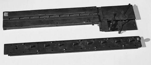
A part of the patent model of the second machine of Barbour (Courtesy of the Smithsonian Institution)
The device (overall measurements: 2.5 cm x 41 cm x 9.1 cm) has a rectangular wooden base with nine grooves in it. The rightmost groove contains a rectangular brass plate with nine rows of teeth in it. The first row has one tooth, the second, two, and so forth. This plate has a metal handle, marked with the digits from 1 to 9, that can be pulled forward to enter a digit.
To the right of the grooved wooden base and its metal plate is another brass plate on which is mounted a mechanism for controlling a slide that is supposed to move over the rectangular plate, carrying out desired arithmetic operations. In this machine, multiplication is carried out by repeated motion of the slide, rather than in a single motion as in Barbour’s first machine.
The third patent of Barbour, applied in 1873 and granted in 1875, described not a direct-multiplication machine, but a calculating machine with a more complex printing device (see the patent drawing below).
The patent drawing of the third machine of Barbour
The U.S. Patent Office model of the third calculating machine of Edmund Barbour is still preserved in the National Museum of American History (see the photo below).
It is a small brass machine with an overall measurement of 5.5 cm x 19 cm x 12.2 cm, which has a rectangular base on which is mounted crosswise a rotating cylinder. The cylinder has nine crosswise grooves that fill somewhat less than a quarter of the surface.
Metal bands separate the grooves into columns, and each column has a set of nine sliding markers that fit in the grooves. Sliding these markers sets a number. There also is an array of pins around the cylinder, which is used in carrying. There are gears on both sides of the cylinder.
The registering mechanism has an open frame that holds three rods. One rod holds four type wheels, and the other two rods hold four gears each. Each type wheel has the numbers from 0 to 9.
The third calculating machine of Edmund D. Barbour (Courtesy of the Smithsonian Institution)
Let’s recap — despite being not implemented in practice (they were simply too advanced for the beginning of the 1870s), the machines of Barbour included some extremely interesting technical solutions and innovations and proved the great constructor imagination of the inventor.
The image featured at the top of this post is ©Unknown author / public domain