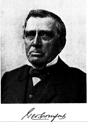
Samuel Comfort (1837-1923) of Morrisville, Pennsylvania, (see biography of Samuel Comfort) attained considerable distinction as an inventor of improvements in mowing and reaping machines, sewing machines, etc., for which he received numerous patents (by age 24, Comfort held over 12 patents in the USA, and Great Britain. Among those patents were US14445 from 1856 for a mower, US16507 from 1856 and US18437 from 1857 for a harvester rake, and US16968 from 1857 for a harvester cutter).

Samuel Comfort: Early Life
Samuel Comfort was born at the Comfort homestead in Bucks County, PA on May 5, 1837. His parents, George and Susan Comfort, were prominent Quakers. Samuel had six siblings.
Comfort received his initial education from private tutors before joining the Trenton Academy, a school for the local elite, in the early 1850s. As a young child, he excelled at math, mechanics, and the sciences.
Samuel Comfort: Military Service, Business, and Foreign Service
From 1861 to 1865, Comfort took part in the Civil War despite the fact that Quakers are pacifists. After the war, he founded Cornell & Comfort, an agricultural machinery manufacturing facility, in Newtown, PA. In 1871, he joined his brothers-in-law’s company Keystone Petroleum Refinery, which later became part of Standard Oil Trust. Comfort spent nine years representing Standard Oil in the U.S. and abroad, including six years in India. While in India, he also served as U.S. vice-consul (1894-1896) and consul (1896-1898) in Bombay.
Comfort served as U.S. vice- and deputy-consul general in Calcutta from 1900 to 1903. By 1904, Comfort was quite wealthy and was able to retire in London where his daughter lived.
Samuel Comfort’s Counting Machine
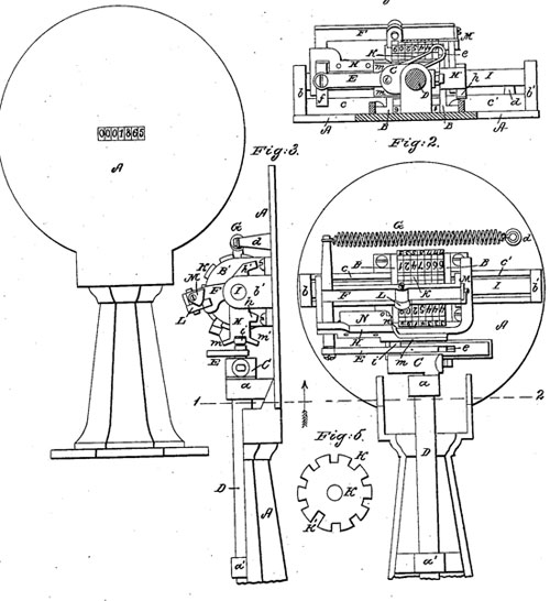
After serving in the Union Army during the Civil War, Major Comfort established himself as a manufacturer of agricultural machinery in Newtown, Pennsylvania, founding the firm Cornell & Comfort. It was during that period that he invented a counting machine — US patent 52681 from 1866 —which we will discuss in depth below.
The operation of the Comfort’s counting machine is as follows (see the lower patent drawing):
US patent 52681
When the crank is in the position shown in Figs. 2, 3, and 4 the bar engages in one of the notches, or k’, in each of the numbering-wheels , holding them all firmly to prevent their being turned upon their centers so as to alter the arrangement of the figures exhibited at the aperture in the face-plate. At the same time the bar , which is secured to the frame , is detached from the numbering-wheels and is free to move with the said frame without communicating any motion to the said wheels.

The spiral spring, contracting, bears the end of the slot in the bar against the crank-pin. The crank and the bar being on centers, the frames are at the extreme limit of their movement toward the projection. The end of the crank-pin engages in the groove in the frame, which latter has completed one-half of its oscillatory movement.
US patent 52681
0n turning the shaft in the direction of the arrow, Fig.4, the crank-pin in the groove causes the frame to turn upon the rod until the lip h’ comes in contact with the ways c’. At this moment the crank-pin leaves the groove and the end of it passes over the surface of the flange; but when the shaft is put in motion, as described, the action of the spring moves the frame , which carries the bar and the frame, with the bar, toward the projection b’.
By this movement the bar is withdrawn from the notch in the wheel which indicates numbers of the denomination of units. As the bar is withdrawn from this wheel the projection of the bar enters one of the notches, or k’, in the same.
If it should enter one of the smaller notches, , the bottom of the notch will bear against the face of the said wheel and stop the farther movement in that direction; but if it should happen to enter one of the larger notches, k’, the larger portion of the bar will pass through the said notch, and the projection will engage the tens-wheel, and if the notch in the tens-wheel should be a large one also, it will pass on through this and enter the hundreds-wheel, and so on for the whole series; but the wheels being in the positions shown in the drawings, the bar will only engage in the units-wheel.
When the frames have been stopped by the bottom of the notch bearing against one of the wheels the crank will continue to revolve, the crank-pin running loosely in the slot in the bar, the end of it passing freely over the face of the flange until it re-enters the groove , carries the frame upon its axis in the opposite direction, turning with it the wheel or wheels, which are engaged with the bar.
When the lip comes in contact with the ways c’ the end of the crank-pin again leaves the groove and traverses over the surface of the flange m’. At some period of this portion of its movement the crank-pin again comes in contact with the end of the slot in the bar, moves the frames and, withdraws the bar, and again registers the numbering-wheels upon the bar.
The crank-pin then re-enters the groove and completes the movement to the point whence it started. The notches in the numbering-wheels are so arranged in respect to the digital numbers marked upon the same that when the figure 9 (nine) is exhibited by any wheel at the aperture in the face-plate the larger notch k’ of that wheel is so situated that the bar may pass through it and engage the wheel of the next higher denomination. Thus the numbers indicated may pass from units to tens, from tens to hundreds, etc.
There is no evidence that Comfort’s counting machine was ever manufactured.
The image featured at the top of this post is ©Unknown author / public domain
