Key Points:
- Reichold was a expert at woodworking, and he carved and constructed wooden clocks and other things including an arithmetic machine.
- The machine of Reichold performed the following 4 basic types of calculations: addition, subtraction, multiplication, and division.
- The internal mechanism is made up of an intricate system of gear-wheels, cranks, disks, ratchets, pins, wheels, pins, and more. As the crank is turned, the mathematical operations are calculated.
The arithmetic machine of Johann Reichold
The article was written with the expert help of
Mr. Stephan Weiss,www.mechrech.info
Until now, the information about the calculating machine of the German parson Reichold was very scanty. It is only mentioned in the famous book “Die Rechenmaschinen” of Ernst Martin from 1925, but without any details. It seems the only reliable information for the arithmetische maschine (arithmetic machine) of Reichold can be found in a book from Johann Paul Bischoff, written in 1804, but published as late as in 1990—Versuch einer Geschichte der Rechenmaschine (Attempt at a History of Calculating Machines), publisher: Systhema-Verlag, editor: Stephan Weiss.
Johann Paul Bischoff (1736—1811) (see biography of Johann Bischoff) was a civil clerk in the court in Ansbach, Bavaria. After spending many years in collecting information, in 1804 he finished a manuscript for a book (including 26 drawings), that is a comprehensive account of the history of computing tools and methods used until then. It contained a meticulous compilation of virtually everything known for calculating methods and devices, from calculation with fingers to the calculating machines of Pascal, Morland, Grillet, Leibniz, Poleni, Lepine, Leupold, Poetius, Boistissandeau, Hahn, Müller and Reichold
After Jacob Leupold’s Theatrum arithmetico-geometricum from 1727, Bischoff actually made the second comprehensive representation in this area. Unlike his predecessor however, Bischoff’s work has never been printed in his time.
From the end of 19th century, the manuscript was kept in the library of Technical University of Berlin. Part of this library was destroyed in a fire during the WWII (in 1943), the remaining part was carried away by Russian soldiers at end of the war. Thus the manuscript was lost. Only two undated transcripts from the beginning of 20th century survived to our time (may be there is something more in Russian archives?). Besides detailed text descriptions, Bischoff’s manuscript also contained many tables, sketches and large coloured drawings. Unfortunately except of some sheets most of them are lost. Only poor quality black and white photographs of all drawings, taken in the beginning of 20th century, survived to the present.
It is known that in the last quarter of the 18th century Bishoff has undertaken several long trips to take a look personally at the calculating machines, of which he had heard, in order to describe them in his book. Admittedly this is the case also with the machine of Reichold, otherwise Bishoff wouldn’t have gained so detailed information about the mechanism, given in the book. Moreover, Ansbach is only some 30 km south from Dottenheim, where Reichold lived.
Too little is known about the life of Johann Reichold (1753-1798) (see biography of Johann Reichold).
Just like his compatriot Philipp Matthäus Hahn, Reichold was a bright-minded parson, who was not so interested in theological problems, but preferred to spend his time studying and lecturing sciences, especially philosophy, mathematics and engineering. It is possible Reichold to have been acquainted with and inspired by the calculating machine of Hahn, not only because it was a quite popular device, described in several publications, but also because the Hahn’s brother-in-law Johann Schuster (who made several machines by Hahn’s design) from 1794 ran a workshop in Ansbach.
Reichold obviously had a rich experience in woodwork, making wooden clocks and other instruments. That’s why the copy of the Reichold’s arithmetic machine, seen by Bishoff, was not a metal one, but was made entirely of pear wood (pear wood even now is one of the preferred materials in the manufacture of high-quality woodwind instruments and furniture).
Probably due to its wooden construction, the machine was quite big—it has a cylindrical form, 7.5 cm height and about 27 cm diameter (see the lower image). Let’s mention only, that almost all other calculating machines from that time were big, for example the first calculating machine of Anton Braun, although made by metal, was even bigger—40 cm diameter, 21 cm height.
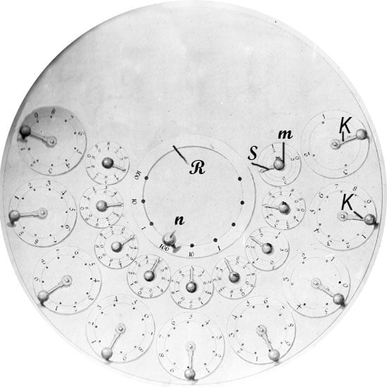
Figure 1: The machine of Reichold (upper view) © Stephan Weiss, www.mechrech.info
The device has two rows with nine graduated number disks in each row. In the center of outer number disks, used during entering of the numbers into machine, are mounted axes, on which are fixed cranks (marked with on Figure 1) and gear-wheels (marked with A, A’ and A”) (see the Figure 2 below). In the center of inner (smaller) number disks are mounted axes, on which are fixed pointers (marked with ), knobs (), ratchet-wheels (C, C’, C”), gear-wheels and star-wheels.
The motion (rotation) from the input mechanism (bigger disks) to the resulting mechanism (smaller disks) is transferred by engaging the teeth of gear-wheels to the teeth of gear-wheels (on Figure 2). The mechanism of each digital position is connected also by means of the star-wheel and teeth (see Figure 3 and 4) to the mechanisms of the next position (if any), in order to propagate tens carry operations, when needed.
The number disks in first (right) pair are divided into four parts, numbered 0, 1, 2 and 3. The second pair disks are decimal (base ten), divided into 10 parts. The third pair disks are divided in six parts (numbered 0, 1, 2, 3, 4 and 5). The pairs from 4th to 9th are decimal. The graduation of the disks was made according to the monetary system adopted throughout the southern states of the Holy Roman Empire in 18th century (240 Pfennige = 60 Kreuzer = 1 Gulden). The first pair of number disks is used for presenting Pfennige (4 Pfennige made a Kreuzer), the second and the third pairs of disks are used for presenting Kreuzer (60 Kreuzer made a Gulden), and the remaining 6 are used for Gulden and decimal calculations.
The crank () in the center of each bigger number disk rotates the axis and the gear wheel () below the disk. Under each digit on the bigger number disks there is a small hole, into which can be inserted a pin, thus limiting (stopping) the rotation of the crank. Under zero digit of each disk there is also a pin, which abuts the crank, so that it can be turned only up to this pin and not further in circles. So when we want to enter a number in this position, we have to put a pin in the proper hole, and to rotate the crank from zero position to the pin and back, from the pin to zero.
The smaller (inner) number disks are divided at the same scale, as the larger disks (i.e. first disk in 4 parts, second in 10 parts, etc.), however, they contain a double row of digits—black digits for addition and multiplication, and red digits for the subtraction and division. Black digits are actually placed as a complement to nine of red digits, e.g. black zero is near red 9, black 1 is near red 8, and so on.
In the middle of smaller disks are mounted pointers, which are used for presenting the result of calculations. The pointers also can be moved with the aid of wooden knobs (marked with in the Figure 1), and thus, can be set to any number.
In the center of the front panel is mounted an immovable ring (marked with ) with 9 holes, into which can be inserted a small pin (marked with ). This ring is used to describe the place where one left off during the operation. On this ring also are marked the values of the adjacent number disks.
Let’s examine the modus operandi of the machine, performing the 4 basic arithmetical operations (addition, subtraction, multiplication and division).
1. Addition.
Let’s add 365 Gulden, 50 Kreuzer and 3 Pfennige to 219 Gulden, 19 Kreuzer and 1 Pfennig. Firstly we have to enter the first addend (365 G, 50 K and 3 P) into the smaller number disks, using knobs of the pointers and black digits (black digits are used for addition and multiplication, red digits for subtraction and division). So we set the pointer of the right smaller disk to show 3 (we have 3 Pfennige). The 2nd disk pointer must be set to 0, the 3rd disk pointer—to 5 (we have 50 Kreuzer). The 4th disk pointer must be set to 5, the 5th—to 6, and the 6th—to 3 (we have 365 Gulden).
Now let’s enter the second addend (219 G, 19 K and 1 P) using the cranks and the bigger number disks. First we have to put the pin into the hole below 1 (we have 1 Pfennig) of the first big number disk and to rotate the crank until it will be stopped by the pin (thus the crank will rotate the axes to 90 degree), and to return the crank back to zero position. The movement from the bigger disk mechanism will be transferred to the smaller, rotating the pointer from 3 (it was 3 Pfennige) to the next position (0), causing a tens carry to be propagated to the next digital position (small disk), which was set to zero Kreuzer, but now will turn to 1.
Using the same manner, we have to enter Kreuzer (19)—9 into the 2nd big disk (causing the 2nd small disk to rotate from 1 to 0, and a tens carry to be propagated to the third small disk, which was 5, but now will go to zero, and another tens carry to go to 4th small disk, which was 5, but now will show 6), and 1 to the 3rd big disk, causing the 3rd small disk to rotate from 0 to 1. As an intermediate result, before entering of the Gulden of 2nd addend, we have now 366 Gulden (in 6th, 5th and 4th small disks), 10 Kreuzer (in 3rd and 2nd disks) and 0 Pfennige (in the last disk). We have only to enter 219 (Gulden of the 2nd addend) using the cranks, causing 1 tens carry to be propagated from 4th to 5th small disk, in order to get the final result—585 Gulden, 10 Kreuzer and 0 Pfennige.
2. Multiplication.
The multiplication was done just like in the other calculating machines from the time, i.e. using consecutive additions. If for example we have to multiply 815 by 9, we have to put the pin under the digit 5 on 4th big disk, and to turn the crank to the pin 9 times. The similar operation must be done for tens and hundreds. If we want to multiply multi-digit numbers, this will require writing down the intermediate multiplication results (multiplying the multiplicand to Ones, Tens, Hundreds, Thousands etc. of multiplier), and adding them one by one, a rather cumbersome operation.
3. Subtraction.
The subtraction is similar to addition, but the red digits must be used instead of black. The minuend must be set into the smaller disks mechanism, using knobs of the pointers and red digits, and then the subtrahend must be entered into the bigger disks mechanism, using the cranks.
4. Division.
The division is even more cumbersome and error-prone operation, than the multiplication, because it was done using consecutive subtractions, and some intermediate calculations are needed, in order to get the final result. The dividend is entered using the red numbers in smaller disks. Then the divisor must be placed under the highest digit of the dividend and deducted from this part of dividend until the same has become smaller than the divisor. Then if the dividend has more digits available, the divisor must be shifted to the right, and the consecutive subtraction to be repeated, and so on, until the entire dividend will become smaller than the divisor.
As you can see, just like the other calculating machines from the time, which are actually simple adding devices, the machine of Reichold is suitable only for addition and subtraction. For multiplication and division it is much more convenient to use other calculating techniques and methods.
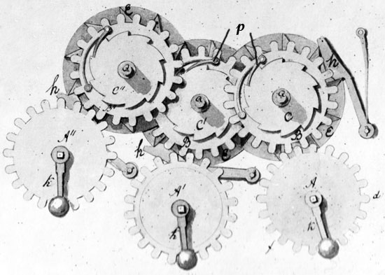
Figure 2: The internal mechanism (general view of gear-wheels) © Stephan Weiss, www.mechrech.info
Internal mechanism of the device.
On the Figure 2 with letters , A’ and A” are marked gear-wheels, fixed on the same axes as the cranks . The wheels are engaged with gear-wheels with the same diameter and number of teeth , which are fixed firmly to the axes of smaller number disks.
Directly above each of the gear-wheels on the same axis are attached ratchet-wheels, which have locking pins and springs (marked with ), mounted on wheels . These locking pins are fixing the ratchet-wheels to the gear-wheels and limiting their rotation in one direction regarding wheels . Ratchet-wheels are not firmly attached to the axes , but only to the pointers. Thus, when we are entering a number in smaller disks mechanisms, rotating the pointers in counter-clockwise direction, this will only rotate on the ratchet-wheel, without affecting the gear-wheel and the star-wheel . However, when a number is entered rotating the cranks forward and backward, then the locking pins and springs, mounted on wheels will engage the ratchet-wheels and will rotate them, together with pointers, thus changing the result.
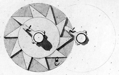
Figure 3: The star-wheel (tens carry mechanism) (© Stephan Weiss, www.mechrech.info
On the same axes , but mounted on some distance below the wheels (see the Figures 3 and 4), are mounted star-wheels (marked with ). The wheels have teeth , which are used for propagating the tens carry to the next axis, as once in each full revolution of the axes will engage the next star-wheel and will rotate it. The wheels have also locking pins and springs (marked with ), which are fixed to the body of the machine, and are fixing the wheels and limiting rotation only to one direction.
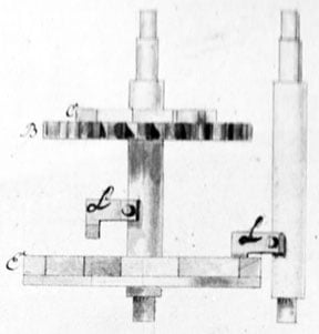
Figure 4: The internal mechanism (side view of gear-wheels) © Stephan Weiss, www.mechrech.info
The star-wheels , just like the ratchet-wheels , are not fixed firmly to the axes , so during the rotation of the cranks they can rotate or not, depending of the direction of rotation and the position of the locking pins
Let’s imagine, that we are going to enter a number in the rightmost wheel , moving the crank from position to , and then back from to (see Figure 2). During the first half of the rotation, from position to , the teeth of wheel will engage the teeth of wheel and will rotate it. At this moment however, the star-wheel will be stopped by the fixing pin and will not follow the movement. The ratchet-wheel will not follow the movement of wheel also, because the locking pin is not limiting the movement of wheel in counter-clockwise direction. So only wheel , but neither the wheel , nor the wheel will follow the movement.
During the second half of the rotation of crank , from position to , the teeth of wheel again will engage the teeth of wheel and will rotate it, but in opposite direction. Now, the wheel will follow the rotation, because in this direction the fixing pin does not limit its rotation. The same is the case with the ratchet-wheel , which will be pushed and rotated by the fixing pin
In this manner, we will manage to transfer the number (motion) to the calculating mechanism and to turn back the crank into the initial (zero) position.
Obviously, the design of the machine is basically simple, but workable, and if the parts had been manufactured precisely and by metal, it could be a much smaller and reliable device. Nevertheless, Reichold must had been a very good constructor, unfortunately struck down young and in his prime.
Literature: Johann Paul Bischoff, “Versuch einer Geschichte der Rechenmaschine”, publisher: Systhema-Verlag, 1990, editor: Stephan Weiss.
The image featured at the top of this post is ©Unknown author / public domain