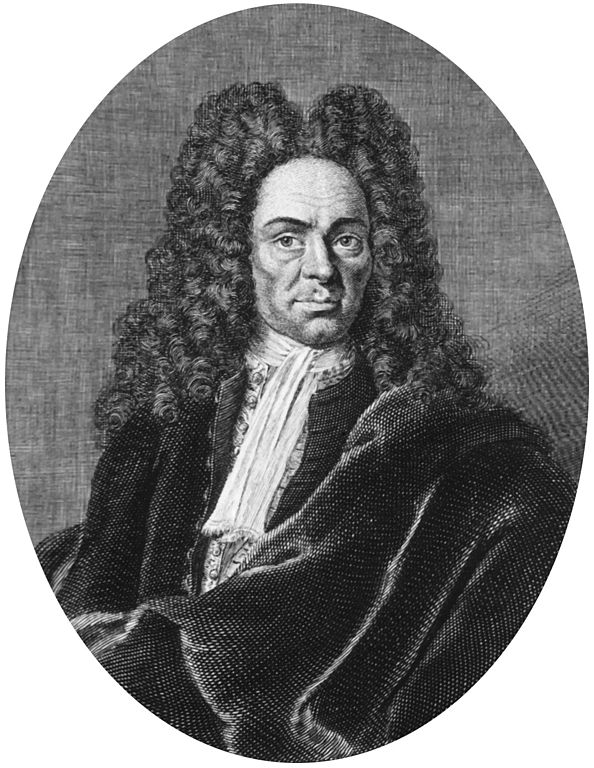
- Jaco Leupold (1674–1727) was a German scientist, instrument maker, physicist, and mathematician who wrote Theatrum arithmetico-geometricum, the best-illustrated work on calculation and measurement published during the eighteenth century.
- The encyclopedia describes and illustrates the calculating devices and machines of Kircher (Schott), Grillet, Leibnitz, Poleni, along with Napier’s rods and several calculation tables.
- Leupold designed his own version of a calculating machine, but no prototype was ever built due to his untimely death.

The Calculating Machine of Jacob Leupold
In 1727, after the death of the prominent German scientist, instrument maker, physicist, and mathematician Jacob Leupold (1674–1727) (see biography of Jacob Leupold) was published the 8th volume of his encyclopedia Theatrum Machinarum. This volume, entitled Theatrum arithmetico-geometricum is the best illustrated work on calculation and measurement published during the eighteenth century. It describes and illustrates the calculating devices and machines of Kircher (Schott), Grillet, Leibnitz, Poleni, along with Napier’s rods and several calculation tables (interestingly enough, Leupold missed the Pascaline, the most famous calculating machine of the time).
It also discusses and illustrates the various analog devices available, including slide rules and sectors, and other calculating and measuring rules, as well as systems of computing using the fingers. In this volume, Leupold mentioned that “he was interested in calculating machines more than 20 years”, and “he had four or five types brought out”, “and that he had been able to show the effect to different friends”. Leupold described also an original calculating machine, designed by himself.
This calculating machine was never manufactured by Leupold, probably because of his early death in January 1727. Later on, the principle of Leupold’s machine would be used by Anton Braun (see machines of Braun), who designed a similar device but also didn’t manage to manufacture his machine, because he also died too young (in 1728). Braun’s machine was finally manufactured by the mechanic Phillippe Vayringe in 1736.
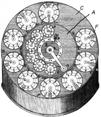
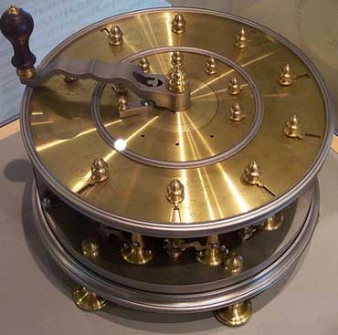
The numbers are entered by means of the 6 small digital wheels, placed around the handle in the middle of the lid. Rotating this handle to a full revolution in a counterclockwise direction will transfer entered in the input mechanism number to the 6 dials (digital positions), placed in the outer ring (marked with in the figure), which present units, tens, hundreds, etc. The result mechanism has 9 positions—the nine dials , mounted on the outside ring (marked with in the figure). The dials have 2 graduations — first is used during the addition and multiplication, second — during subtraction and division. The digits of the result are pointed by special pointer-arrows, which are rotating around the middle of the axes.
On the same axes, but inside of the machine (see the figure below), are placed 10-teeth stop-wheels, which are rotating only in 1 direction (clockwise), and can be fixed by means of the small rod and spring-rod.
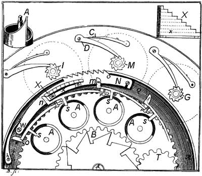
The motion from the input (6 small dials) to the result (9 bigger wheels in the ring ) is transferred by means of the 9-teeth sector teeth strip, which can be rotated around the axis. On the strip, on the plane, perpendicular to its, is attached a thin plate, which is illustrated separately in the upper right part of the figure. The left sideward surface of the plate is straight, the right is formed as 9 steps with the same height. The function of this plate is to raise the teeth-strip, which will engage with the result mechanism and will rotate it. This is done in this way:
Below each one of the entering wheels is placed a ring with a spiral inclined upper surface, which is shown in the upper left part of the figure. Each position of the input mechanism has an eccentric rod (marked with, and), which has a bulge in its upper part, contacting to the plate, and another bulge in its lower part, contacting to the spiral surface of the ring. Rotating one of the 6 entering wheels, thus rotating the appropriate ring, we actually will raise or take down these eccentrics in a plane, perpendicular of the plane of the teeth-strip and parallel to the plane of the plate in this way, that upper bulge will raise and fix in the upper position this plate for different distance, and in this way different number of teeth will be engaged with the top-wheels. In this way, the number of the teeth, to which will be rotated each of these wheels, is determined by the length of the engaging way of the eccentric with the plate
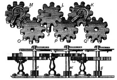
The invented by the Leupold mechanism will become quite popular at the end of the XIX century in several calculating machines, e.g. machines of Dietzschold and Büttner. It will be called Schaltklinke in German, in English it is called switching latch, intermittent contact, adjustable pawl, and selectable ratchet
In the middle of the machine is placed an auxiliary counter, which scale can be seen around the handle. This counter is destined to count the revolutions of the handle.
The tens carry mechanism (see the upper figure) is made in this way: On the same axes, on which are fixed the stop-wheels , , …, are fixed also 10-teeth wheels , , … Between them are placed intermediate wheels , , … Each intermediate wheel has attached a finger, fixed with a spring (, , , …), and in odd-numbered wheels this finger is placed over the wheel of units, while in even-numbered wheels this finger is placed below it. In one revolution of the units-wheel the finger de will rotate to 1/10 revolution the wheel of the tens , and thus the tens carry will be performed. The tens carry form the other wheels will be performed in much the same manner.
In the figure below you can see a modern replica of the Leupold’s calculating machine.
The image featured at the top of this post is ©Unknown author / public domain.